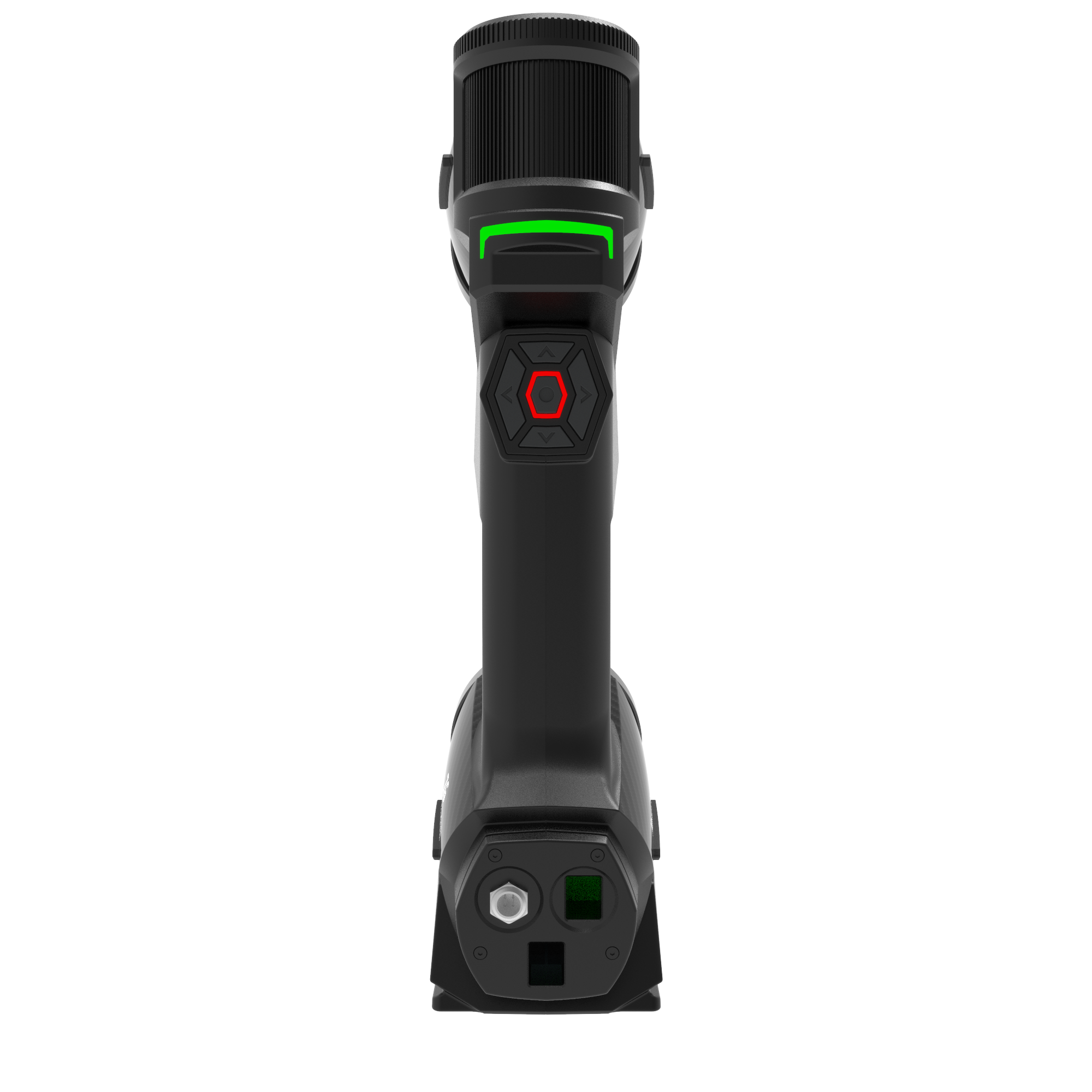
Measuring heavy machinery like turbine housings, maritime engine blocks, and mining equipment traditionally requires hours of prep work or line-of-sight restrictions. Manufacturers lose valuable production time just preparing massive parts for inspection. Conventional 3D scanning relies on applying hundreds of reflective targets or maintaining an uninterrupted line of sight to an external optical tracker. In industrial shop-floor environments, both methods introduce serious bottlenecks, heavy labor demands, and severe operational downtime.
Advanced metrology has recently shifted toward the Tracker-Free & Marker-Free 3D Laser Scanner. By combining global photogrammetry and localized laser scanning, quality assurance teams can now evaluate massive, complex geometries directly on the manufacturing floor. You will learn how this hybrid technology eliminates prep time without compromising volumetric accuracy, enabling agile and highly precise inspections.
Key Takeaways
Zero-Prep Efficiency: Eliminating targets and external tracking setups reduces inspection prep time by up to 80% on large-scale machinery.
Shop-Floor Resilience: Marker-free systems capture data dynamically, remaining unaffected by shop-floor vibrations or line-of-sight blockages.
Hybrid Tracking Technology: A 3D Laser Scanner with Independent Built-in Photogrammetry establishes its own spatial coordinate system, enabling high-precision measurement over large volumes (up to several meters) without accumulating alignment errors.
Evaluation Mandate: Buyers must benchmark these systems using standardized volumetric accuracy metrics (e.g., VDI/VDE 2634) on their actual shop floor, rather than relying solely on optimal-condition spec sheets.
The True Cost of Traditional Tracking in Heavy Manufacturing
Traditional metrology equipment places enormous demands on your workforce before scanning even begins. Applying reference targets to large castings or welded structures creates a massive manual bottleneck. Operators must clean the industrial surface, painstakingly place hundreds of reflective stickers at specific intervals, and verify their placement. After the scan, they must peel off these targets and use chemical solvents to remove the adhesive residue. This tedious process consumes hours. When dealing with an eight-meter excavator boom or a massive wind turbine hub, you lose an entire shift just to preparation and cleanup.
Optical trackers introduce an entirely different constraint known as the line-of-sight limitation. External tracking units must maintain direct visual contact with the handheld scanner. Heavy machinery frequently features deep cavities, sharp undercuts, or complex internal components. When you reach inside a turbine housing, the tracker loses sight of the scanner. Operators must stop the process, carefully reposition the heavy tripod-mounted tracker, and recalibrate the system. These interruptions severely break the inspection workflow and multiply the total time required to capture a single asset.
Industrial manufacturing floors also harbor environmental vulnerabilities. Traditional external tracking setups require rigid stability. If a nearby forklift drives past, floor vibrations can knock the external tracker out of calibration. Temperature fluctuations across a massive facility can also cause micro-expansions in the tracking stands. Teams must wait for thermal equilibrium or constantly perform recalibrations. These strict environmental requirements simply do not align with the chaotic, dynamic reality of active heavy manufacturing plants.
How a Tracker-Free & Marker-Free 3D Laser Scanner Works
Modern metrology bypasses external tracking devices entirely through algorithmic positioning. Handheld devices leverage advanced Simultaneous Localization and Mapping (SLAM) combined with geometric feature tracking. The scanner's software identifies unique geometric features on the object itself—such as edges, curves, and bolt holes. It uses these features as digital anchors. As you move the device, the software continuously matches the live data against these recognized patterns. This process eliminates the need for an external camera or physical stickers to tell the scanner where it is in 3D space.
To measure massive machinery accurately, manufacturers rely on a 3D Laser Scanner with Independent Built-in Photogrammetry. Pure SLAM systems can suffer from "drift," where tiny alignment errors accumulate over long distances. Built-in photogrammetry solves this problem by instantly capturing a large-scale global reference frame. The device shoots a series of wide-angle images to construct a highly accurate volumetric skeleton of the entire object. The laser scanning unit then cross-references its localized surface data against this internal global map. This hybrid approach firmly locks fine details into their correct spatial coordinates, entirely preventing accumulated drift.
This internal architecture enables dynamic referencing during operation. In traditional setups, if the part moves even a millimeter, the scan data becomes corrupted. Because a marker-free scanner relies on the object's own geometry and its internal photogrammetry map, it maintains spatial orientation dynamically. If a crane operator shifts the heavy machinery slightly or if the shop floor vibrates heavily, the software instantly compensates. The digital reference frame moves alongside the physical part, allowing you to scan continuous, flawless data without rigid clamping.
Validating Volumetric Accuracy on Large-Scale Assets
Quality assurance professionals often confuse localized resolution with volumetric accuracy. Resolution defines the smallest surface detail a scanner can capture, like a tiny scratch on a machined flange. Volumetric accuracy measures how perfectly the scanner maintains dimensional precision across a vast distance. You might capture an extremely high-resolution scan of a five-meter ship propeller, but if the volumetric accuracy is poor, the software might digitally warp the propeller blades. Understanding this distinction ensures you evaluate the equipment based on its macro-level precision.
Table: Localized Resolution vs. Volumetric Accuracy
Metric
Definition
Primary Impact on Heavy Machinery
Common Measurement Range
Localized Resolution
The density of points captured within a specific localized area.
Capturing fine surface defects, textures, and small hole diameters.
0.01 mm to 0.1 mm
Volumetric Accuracy
The dimensional precision maintained over the entire volume of the object.
Ensuring large-scale assembly alignment, parallel surfaces, and overall CAD variance.
0.02 mm + 0.015 mm/m
You must evaluate your metrology equipment against stringent industry standards. Relying purely on marketing specifications leads to inaccurate shop-floor results. Look for devices certified under ISO 17025 laboratory standards. More importantly, demand performance data tested against the VDI/VDE 2634 Part 3 standard. This rigorous German engineering framework specifically tests optical 3D measuring systems using calibrated artifacts over multiple lengths and angles. Equipment passing this standard provides verifiable confidence when inspecting critical multi-million-dollar assets.
Engineers naturally express skepticism about completely markerless scanning on featureless geometries. If you scan a perfectly smooth, five-meter polished cylinder, SLAM algorithms struggle to find unique geometric features to track. Transparently, extremely repetitive or completely flat surfaces may still require a scattering of reference features. However, hybrid systems actively mitigate this. Built-in photogrammetry bridges large featureless gaps by anchoring the data to the structural edges of the part. You rarely need to coat the entire object in targets; applying just a handful at key transition points gives the algorithm everything it needs.
Core Buying Criteria for a High Resolution 3D Laser Scanner
Material adaptability determines whether a scanner belongs on a real manufacturing floor. Heavy machinery ranges from deeply dark forged iron to highly reflective machined aerospace alloys. Traditional scanners fail on these surfaces, forcing operators to coat the parts in dulling spray. This spray alters dimensional accuracy and requires extensive cleaning afterward. Modern equipment utilizes optimized blue-laser technology and smart exposure algorithms to measure shiny or black surfaces directly. Evaluating this adaptability ensures you preserve part integrity while saving hours of preparation.
Software processing power and interoperability represent another critical buying factor. Capturing massive machinery generates enormous amounts of point cloud data. You need native software capable of handling this without crashing your workstation. When investing in a High Resolution 3D Laser Scanner, carefully examine how quickly it generates the mesh polygon model. Beyond native processing, check for seamless interoperability. The scanner's software must easily export clean STL or IGES files directly into industry-standard inspection platforms like PolyWorks or Geomagic Control X for automated CAD-to-part comparison.
Reflective Surface Capability: Verify the scanner can capture un-sprayed machined metals.
Dark Material Performance: Ensure clear data capture on cast iron and carbon fiber.
Mesh Generation Speed: Test the software's rendering speed on files exceeding 10 gigabytes.
Software Interoperability: Confirm direct plugin support for major GD&T inspection software.
Ergonomics and portability often dictate the actual success of your metrology program. You cannot easily move heavy machinery into a temperature-controlled Coordinate Measuring Machine (CMM) room. You must bring the scanner into cramped welding cells, high atop scaffolding, or deep inside maritime engine blocks. Evaluate the physical weight of the scanner to prevent operator fatigue during long shifts. Assess battery life and whether you can hot-swap power sources without losing scan data. A compact operational footprint allows your team to maneuver effectively in highly confined industrial spaces.
Implementation Risks and Rollout Best Practices
Transitioning to advanced metrology requires proactive operator training. Removing the burden of stickers and tripods makes scanning physically easier, but operators must still understand the underlying science. They need training on optimal scanning techniques to ensure absolute data integrity. If they hold the scanner too far away, accuracy drops. If they scan at extreme oblique angles, the laser reflects poorly. Proper training instills a steady, sweeping motion. Operators learn how to continuously build the mesh while monitoring the real-time software feedback to avoid missing critical geometric data.
Data management infrastructure poses a significant hidden risk. High-resolution scans of an entire wind turbine blade generate immense digital files. Most standard engineering laptops will crash when attempting to process these meshes. You must upgrade your workstation computing power, specifically investing in high-end GPUs and substantial RAM. Furthermore, establish robust network storage protocols. Archiving these quality control files for compliance requires fast local network speeds and scalable server storage to prevent data bottlenecks in your IT department.
Conduct an Environmental Audit: Map out the tightest spaces and lighting conditions where inspections will occur.
Upgrade Hardware Processing: Procure workstations with professional-grade graphics cards and at least 64GB of RAM.
Establish File Naming Protocols: Create a standardized naming convention for archiving massive point cloud datasets.
Demand an On-Site PoC: Force the vendor to prove the equipment on your actual floor, not in a lab.
Always demand an on-site Proof of Concept (PoC) before procurement. Metrology vendors love showcasing their equipment on perfect, matte-gray artifacts in climate-controlled showrooms. Real manufacturing environments feature dust, poor lighting, and vibrating floors. Invite the vendor to your facility. Ask them to scan your most complex, highly reflective, or hardest-to-reach heavy machinery. They should demonstrate the scanner's capability in your actual working environment. This benchmark test provides the only true validation of the scanner's speed, accuracy, and operational viability.
Conclusion
Transitioning to a marker-free workflow fundamentally transforms how manufacturing facilities handle quality control. By eliminating tedious target application and removing line-of-sight constraints, you drastically reduce machine downtime. Engineering teams capture complex structural data dynamically, avoiding the bottlenecks of external optical trackers. This approach turns a multi-hour inspection chore into a rapid, highly precise operation.
Balancing shop-floor usability with volumetric accuracy remains the most important factor in your metrology strategy. Equipment featuring built-in photogrammetry specifically addresses the drift issues found in older markerless systems. You gain the freedom of movement without sacrificing the tight tolerances required for multi-meter heavy machinery assembly.
Take immediate action by auditing your current inspection bottlenecks. Calculate the hours your team wastes applying targets or repositioning tripods. Reach out to a metrology specialist to schedule a technical consultation. Demand a rigorous on-site benchmark test to validate scanner performance against your specific surface types and GD&T requirements.
FAQ
Q: Can a marker-free scanner measure highly reflective or black machined parts?
A: Yes. Modern blue-laser technology and optimized exposure algorithms allow these scanners to capture shiny or dark heavy machinery without the need for chalk or dulling sprays, preserving part integrity.
Q: How does the scanner maintain accuracy over a 10-meter wind turbine component?
A: By utilizing a 3D Laser Scanner with Independent Built-in Photogrammetry. The photogrammetry system shoots a volumetric "skeleton" of the part, while the lasers fill in the high-resolution surface data, preventing error accumulation over distance.
Q: Does "tracker-free" mean there is no calibration required?
A: No. While you do not need to calibrate a relationship between the scanner and an external optical tracker, the handheld unit itself still requires periodic calibration (often a quick 1-minute process using a certified calibration board) to maintain ISO-certified accuracy.
Q: Is CAD software included with these high-resolution scanners?
A: Most industrial scanners include proprietary data acquisition software to generate the STL/point cloud mesh. However, dimensional inspection (GD&T) or reverse engineering typically requires third-party software integration, which should be verified during the procurement phase.