Unmapped tool wear in plastic injection molding leads to compounding costs: flash, dimensional non-compliance, and unexpected production downtime. You can quickly lose control of process stability when molds degrade unseen. Parts reject rates climb before anyone notices the root cause. Traditional metrology struggles with the complex freeform surfaces of molds. Fixed coordinate measuring machines (CMMs) or manual gauges require pulling the tool from the press. They disrupt the manufacturing floor and offer limited data points. Taking the tool out of service creates unacceptable production bottlenecks.
3D scanning enables rapid, proactive wear mapping through CAD-to-part deviation analysis. However, selecting the right hardware is critical to yielding trustworthy data on machined steel. Laser type and resolution dictate the quality of your inspection results. By adopting optical metrology, manufacturers turn a blind spot into a highly controlled workflow. You will learn exactly how to leverage this technology to monitor mold health effectively.
Key Takeaways
Workflow efficiency: 3D scanning maps wear by overlaying real-world mesh data onto nominal CAD models, generating intuitive 3D color maps of surface deviation.
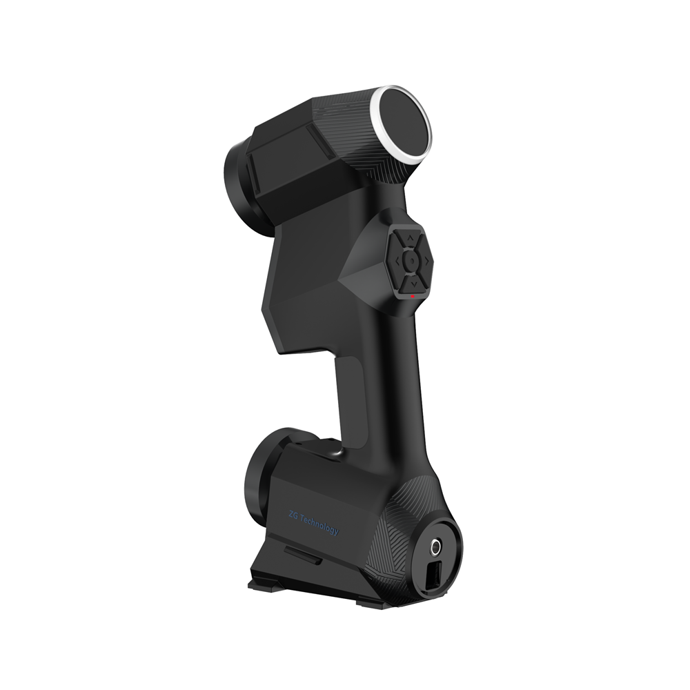
Hardware requirements: Machined, reflective tool steel necessitates a Smart Handheld Blue Laser 3D Scanner to capture data accurately without applying degrading developer sprays.
Evaluation focus: Buyers must weigh volumetric accuracy, mesh resolution at sharp edges (parting lines/gates), and software compatibility when shortlisting a 3D Scanner for Mold Inspection.
Implementation reality: Success requires acknowledging line-of-sight limitations in deep cavities and investing in proper inspection software training.
The Business Cost of Unmapped Mold Wear
Abrasive resins inevitably erode gating systems, draft angles, and parting lines. Materials like glass-filled nylon act like sandpaper under high injection pressures. Thermal cycling causes microscopic surface fatigue over thousands of shots. Extreme clamping forces slowly crush delicate shut-off areas. If you do not map this gradual deterioration, you will experience sudden spikes in defective parts. Unmapped wear forces process engineers to alter injection pressures artificially. This temporary fix eventually causes severe flash or short shots. The core problem remains hidden inside the degraded mold cavity.
Legacy inspection methods present severe limitations for modern production floors. Highly accurate fixed CMMs require removing the mold from production. This creates significant manufacturing bottlenecks. CMMs capture discrete data points using touch probes. They cannot easily map full organic surfaces or complex freeform cavities. You end up with blind spots in your data. Alternatively, visual inspection and resin casting offer subjective results. Technicians rely on physical feel or visual guesswork. This approach is non-repeatable. It completely lacks the quantifiable data necessary for predictive maintenance routines.
A modern metrology solution must meet specific operational success criteria. The hardware must be portable. Technicians need to use it directly on the shop floor or near the press. It must deliver sub-millimeter accuracy to catch microscopic material loss. Furthermore, it must capture comprehensive full-surface data. Isolated touch-points simply do not provide enough context for complex tooling. By capturing the entire geometry, engineers can spot cascading wear patterns.
Mold Inspection Metrology Comparison
Metrology Method
Data Density
Portability
Setup Time
Best Application
Fixed CMM
Low (Discrete points)
None (Lab only)
High
Absolute geometric tolerances
Visual / Casting
Subjective
High
Low
Quick go/no-go checks
Optical 3D Scanning
High (Full surface mesh)
High (Shop floor)
Low
Comprehensive wear mapping
Step-by-Step: Mapping Surface Deviation with a 3D Scanner
The first phase requires meticulous data acquisition. You begin by scanning the tool components. Using a 3D Scanner for Mold Inspection allows you to capture physical geometry rapidly. The laser sweeps across the worn mold cavity, core, and sliding components. Cameras track the laser line deformations. The hardware translates this optical feedback into a high-density point cloud. The onboard software instantly meshes these points into a continuous digital surface. You capture millions of precise measurements in minutes.
Next, you move to alignment and registration. You import the raw scan data into dedicated inspection software. Industry-standard programs include Geomagic Control X or PolyWorks. The software overlays the scanned mesh onto your original nominal CAD file. You typically execute a best-fit alignment first to see overall deviation. For tooling, datum-based alignment is often more critical. You align the scan using the unmachined datums or mounting plates. This simulates exactly how the mold sits inside the injection press.
Deviation analysis forms the core of the wear mapping process. The software generates a vivid 3D topological color map. This visual tool makes complex metrology data instantly understandable.
Green: Areas colored green sit perfectly within your designated tolerance band. The geometry matches the CAD file.
Red/Yellow: Warm colors indicate positive deviation where material was added. On a mold, this usually signifies polymer buildup, baked-on off-gassing, or rust.
Blue: Cool colors represent negative deviation where material was lost. This highlights critical tool wear, abrasive erosion, or impact damage.
Finally, you must translate this visual data into actionable reporting. You can export specific 2D cross-sections to examine draft angles. You can extract precise GD&T measurements for critical gating dimensions. Tracking this wear trend data over multiple production runs is vital. It dictates precisely when the mold needs proactive maintenance. Data tells you whether to schedule localized laser welding, surface polishing, or total cavity replacement.
Why a Smart Handheld Blue Laser 3D Scanner is the Metrology Standard
Not all 3D scanning technologies work well on tooling steel. Older structured light systems struggle significantly with highly reflective surfaces. P20 or H13 machined tool steel scatters standard light patterns. To fix this, operators often apply dulling developer sprays. These sprays introduce a fatal flaw for precision molds. They add microscopic layers of thickness to the surface. A typical chalk spray adds 5 to 15 microns of artificial material. This immediately invalidates your micron-level metrology measurements.
Modern hardware solves this optical challenge natively. A Smart Handheld Blue Laser 3D Scanner utilizes a much shorter wavelength. Blue light minimizes speckle noise heavily. The high-intensity laser cuts through shiny reflections and dark surface finishes. You do not need to apply degrading developer sprays. The scanner captures the raw, pristine steel surface exactly as it exists.
Portability transforms the inspection environment completely. Handheld systems empower technicians to map wear directly on the shop floor. Factory environments are notoriously harsh. Injection presses cause heavy floor vibrations. Temperatures fluctuate drastically near the cooling systems. Handheld scanners counter this through dynamic referencing. You apply small optical tracking targets to the mold base. The scanner constantly calculates its position relative to these targets. If a forklift drives by and shakes the floor, the scanner automatically compensates. The data remains perfectly locked and accurate.
Speed to data defines the true value of handheld scanning. Traditional metrology requires tedious logistical planning. Moving a 5,000-pound tool block into a temperature-controlled metrology lab wastes hours. Handheld scanners eliminate this transport entirely. You walk the scanner to the press, capture the data, and generate the color map. You make maintenance decisions in minutes rather than days.
Core Evaluation Criteria for High-Resolution Tooling Scanners
Evaluating scanning hardware requires understanding the distinction between resolution and volumetric accuracy. Volumetric accuracy ensures the overall macro-dimensions of the tool block are correct across its length. However, resolution dictates the scanner’s ability to capture micro-features. Molds contain extremely sharp edges, subtle micro-textures, and intricate cooling vents. If your scanner lacks resolution, these sharp corners will look rounded in the data. Investing in a High Resolution Laser 3D Scanner is mandatory. It ensures you can inspect tight radii, parting lines, and delicate gate geometries accurately.
Hardware is only as useful as its software ecosystem. You must evaluate interoperability carefully. Check whether the scanner exports standard mesh formats like STL or PLY. Ensure it integrates natively with industry-standard inspection software platforms. Some manufacturers attempt to lock you into a proprietary software ecosystem. This limits your ability to share data with external toolmakers. Open-architecture systems provide much better long-term flexibility.
Data processing speed heavily impacts daily workflow efficiency. Assess the hardware's onboard processing capabilities before buying. A modern Smart Handheld Blue Laser 3D Scanner performs mesh generation calculations internally. It processes the point cloud in real-time. This heavily reduces the computational load on your connected laptop. The inspection loop speeds up drastically. Your quality technicians spend more time analyzing wear and less time waiting for progress bars.
Essential Evaluation Metrics
Evaluation Metric
Target Specification
Why It Matters for Molds
Laser Source
Blue Laser (Class 2M or similar)
Eliminates the need for thickness-adding sprays on P20 steel.
Mesh Resolution
0.02 mm to 0.05 mm
Captures sharp parting lines without smoothing out crucial edges.
Volumetric Accuracy
Sub-0.05 mm per meter
Prevents dimensional drift across large, multi-cavity tool blocks.
Software Output
Open formats (STL, PLY, OBJ)
Guarantees compatibility with Geomagic, PolyWorks, or native CAD.
Implementation Realities: Risks and Operational Constraints
Despite its advantages, 3D scanning remains a strictly optical technology. It suffers from inherent line-of-sight limitations. The laser and the tracking cameras must physically "see" the geometry to map it. Deep, narrow cavities pose a significant challenge. Conformal cooling channels or severe undercuts will drop out of the scan data. When the angle becomes too steep, the laser cannot return to the sensor. To solve this, technicians often use casting compounds. You pour resin into the blind hole, cure it, extract the casting, and scan the physical plug instead.
The software learning curve catches many engineering teams off guard. Operating the physical scanner is highly intuitive. Most technicians master data capture in a few hours. However, advanced mesh-to-CAD inspection is complex. Setting up proper datum alignments requires deep metrology knowledge. Automating the workflow with macro routines takes significant practice. You must invest in dedicated inspection software training to realize the full value of the hardware.
Equipment maintenance is another critical implementation reality. Shop floor environments expose sensitive optics to dust, oil, and impacts. Scanners require rigorous, regular calibration routines to maintain their certified accuracy. The calibration process usually takes only a minute using a provided artifact board. Additionally, operators must apply optical targets carefully. Placing a target directly over a critical parting line obscures that geometry from the scan. Proper target placement requires thoughtful planning before pulling the trigger.
Conclusion
Transitioning to 3D scanning for mold inspection shifts maintenance from a reactive guessing game to a predictable, data-driven process. By analyzing color-coded deviation maps, your team can catch microscopic wear before it causes major production defects. You eliminate blind spots and drastically reduce press downtime.
When defining your shortlisting logic, strictly prioritize blue laser technology for reflective tooling steel. Demand high mesh resolution to capture delicate parting lines and gates. Furthermore, require live software demonstrations using your own complex CAD models. Never rely solely on a manufacturer's perfectly staged test pieces.
Your immediate next step is to request a Proof of Concept (POC) from scanner manufacturers. Have them scan one of your actual worn molds directly on your shop floor. This validates their accuracy claims, surface handling capabilities, and workflow speed under your specific environmental conditions before you commit to a purchase.
FAQ
Q: Can a 3D scanner measure deep ribs and blind holes in a mold?
A: Only up to a certain depth-to-width ratio. Because laser scanning requires a clear line of sight from the cameras to the laser line, very deep or narrow features may experience data dropout and require alternative probing methods.
Q: Do I need to apply scanning spray to injection molds?
A: Generally, no, if you are using a modern blue laser scanner. Older red laser or structured light systems often require spray to manage reflectivity, which introduces unacceptable dimensional deviations (typically adding 5-15 microns of thickness).
Q: How accurate are handheld laser scanners compared to traditional CMMs?
A: While fixed CMMs remain the gold standard for absolute accuracy (often sub-5 microns), industrial handheld laser scanners typically achieve accuracies between 0.02 mm and 0.04 mm, which is more than sufficient for mapping standard tool wear while offering vastly superior speed and portability.