Manufacturers lose countless hours applying and removing target stickers on massive industrial parts. Operators constantly wrestle optical tracker setups. They battle line-of-sight interruptions daily on crowded shop floors. You need instant-acquisition scanning for both complex reverse engineering and rapid quality control. Rigid physical constraints actively sabotage your production agility. We see an industry-wide shift toward markerless measurement technologies. They solve this exact workflow bottleneck. Evaluating the MarvelScan Tracker-Free Marker-Free 3D Laser Scanner reveals more than just a hardware upgrade. Buyers use it to balance metrology-grade accuracy against demanding operational timelines. In this guide, you will learn how inside-out tracking eliminates prep work. We will break down key evaluation criteria. You can see if markerless workflows fit your specific shop floor environment. Finally, you will discover the practical implementation realities of abandoning reference markers entirely.
Key Takeaways
Zero-Prep Efficiency: Eliminates the labor-intensive application of reference markers and avoids the line-of-sight limitations of external optical trackers.
Metrology-Grade Reliability: Maintains high volumetric accuracy through advanced built-in photogrammetry and sophisticated tracking algorithms.
Workflow Integration: Reduces part-to-mesh time by up to 80% for large-scale, complex geometries (e.g., aerospace, automotive, heavy casting).
Evaluation Truth: While marketed as marker-free, understanding surface geometry requirements is critical to determining if this system fits your specific use case.
The Business Cost of Traditional 3D Scanning Setup
Handheld scanners traditionally demand rigorous and exhausting part preparation. You spend hours applying thousands of sticky markers across massive geometries like aerospace wings or heavy cast-iron engine blocks. Later, you spend even more time removing them. This hidden labor heavily drains your highly paid engineering resources. Tracker-based setups impose rigid physical boundaries around the measurement zone. Line-of-sight breakages halt your progress instantly when an operator steps between the camera rig and the probe. Furthermore, these external tracker systems consume massive shop-floor footprints. They require dedicated, cordoned-off inspection zones.
A successful upgrade slashes this prep time drastically. However, you cannot sacrifice standard metrology compliance. Modern production requires equipment to hit strict benchmarks like VDI/VDE 2634 Part 3, which governs optical 3D measuring systems. Your success criteria hinge on maintaining high-end accuracy while successfully ditching the physical constraints. The transition to marker-free scanning only makes sense if the data remains utterly reliable for downstream inspection.
Removing these constraints unlocks dynamic, versatile scanning. You can easily digitize tight vehicle interiors where a traditional tripod rig cannot see. You navigate narrow walkways along active manufacturing lines. You no longer haul bulky equipment around the facility. The traditional workflow forces you through several wasteful steps that markerless technology eliminates:
Surface cleaning and aggressive chemical degreasing.
Manual marker application across massive, complex physical geometries.
Careful scanning routines designed to avoid reference point damage.
Painstaking post-scan marker removal using scrapers.
Secondary surface cleaning to prevent chemical residue from ruining subsequent paint or coating processes.
Upgrading to sophisticated markerless systems allows your team to bypass these redundant phases completely. You grab the scanner, aim it at the part, and acquire actionable data instantly.
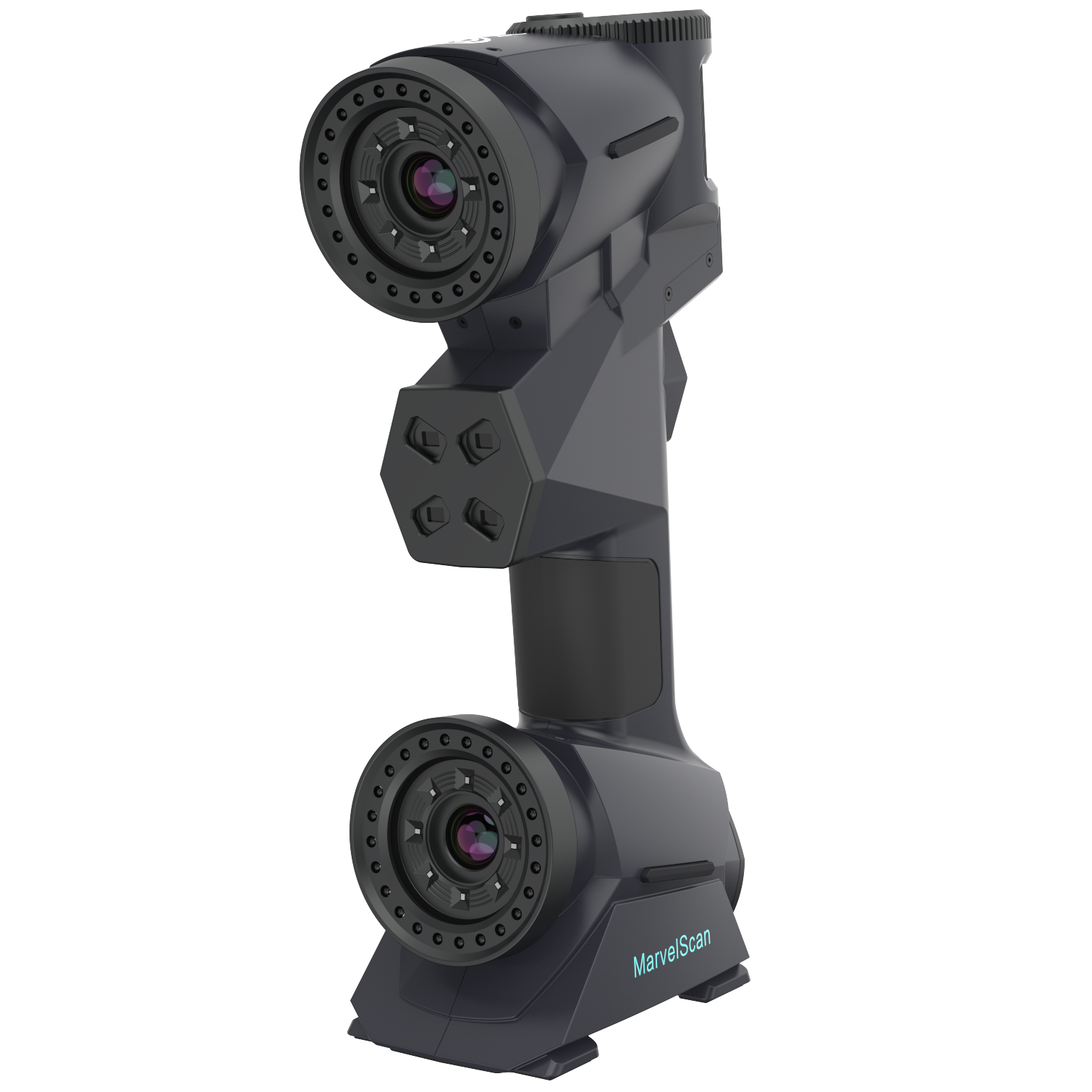
Unpacking the MarvelScan Tracker-Free Marker-Free 3D Laser Scanner Technology
Most optical trackers rely on an outside-in architecture. Fixed external cameras track a localized scanning probe. The MarvelScan Tracker-Free Marker-Free 3D Laser Scanner flips this paradigm completely. It utilizes a highly advanced inside-out tracking methodology. Internal cameras read the physical part's geometric features continuously. They process this unique geometry instantly to orient the device in 3D space. This acts similarly to SLAM (Simultaneous Localization and Mapping) technology, but optimized for sub-millimeter metrology applications.
Multiple intersecting blue laser crosses capture incredible surface detail. Blue light features a much shorter wavelength than traditional red lasers. It handles shiny, reflective, or pitch-black surfaces easily. You avoid messy scanning spray altogether. Here are the core operational benefits of this specific blue laser setup:
Superior mesh resolution on sharp edges and complex mechanical curves.
High-contrast adaptability for aggressively dark or highly reflective metal finishes.
Cleaner work environments without aerosol developer sprays contaminating the shop floor.
Enhanced signal-to-noise ratio, resulting in cleaner raw point clouds.
Large objects usually cause error accumulation over distance. Scanning a three-meter automotive chassis frame often results in volumetric drift. MarvelScan prevents this through an integrated photogrammetry system. It autonomously locks global spatial positioning across large objects. This secures the measurement framework. You maintain extremely tight tolerances across large-scale aerospace castings or heavy machinery components without employing an external scale bar kit.
Sheet metal and machined parts contain critical hole coordinates. Capturing these conventionally takes immense time. Built-in hole flash technology captures these coordinates instantly. The scanner flashes specific light patterns. It measures multiple hole centers simultaneously, accelerating sheet metal inspection workflows dramatically.
Evaluation Criteria: Accuracy, Scalability, and the "Marker-Free" Reality
Large parts stretching over two meters require strict deviation checks. You must evaluate scanning speed versus volumetric accuracy carefully. Standard tracker setups hold global accuracy exceptionally well across massive volumes. The built-in photogrammetry inside the scanner rivals this capability. It delivers rapid data acquisition without letting volumetric deviation spiral out of control. When assessing metrics, always request deviation data for lengths exceeding your largest typical part.
We must build trust by addressing the featureless surface caveat openly. Marker-free technology has practical physics limits. Large, completely flat, or featureless surfaces challenge the tracking algorithm. A perfectly blank sheet metal panel lacks distinct geometry. The scanner cannot anchor its spatial position effectively on a featureless plane. In these specific cases, you might still need sparse markers. You could also place random geometric aids, like magnetic blocks, around the part to maintain tracking. Transparency here ensures you deploy the tool correctly and set realistic expectations for your engineering team.
Shop floors experience constant environmental stress. Heavy stamping presses cause severe vibrations. Ambient lighting changes as bay doors open throughout the day. Temperatures fluctuate drastically between morning and afternoon shifts. Rigid tracker systems often fail here. They lose calibration easily when the tripod bumps or the temperature shifts the rig. A standalone handheld scanner adapts far better. It moves fluidly with the operator. You achieve reliable results directly on the active manufacturing floor, eliminating the need to haul heavy parts into a climate-controlled lab.
MarvelScan vs. Alternative Metrology Approaches
Optical tracker systems from legacy brands dominate certain heavy-industry sectors. They offer exceptional accuracy. However, they demand a massive physical footprint. They restrict portability significantly. Line-of-sight restrictions frustrate operators working inside large structures, like aircraft fuselages or boat hulls. Furthermore, initial capital expenditure for these complex rigs remains extremely high.
Direct competitors offer similar markerless promises. When evaluating alternative handhelds, frame your comparison around the native software ecosystem. Check the raw scan rate, typically measured in lines per second or points per second. Compare the ultimate mesh resolution capabilities. Finally, rigorously test the proprietary tracking algorithms. Not all markerless algorithms perform equally when encountering aggressively shiny surfaces or smooth transitions.
Provide a logical shortlisting framework for your engineering buyers. Choose tracker-free and marker-free systems if portability drives your workflow. They excel when setup speed dictates project success. Conversely, stick to traditional trackers if you scan highly repetitive, featureless geometries. Fixed robotic cells automating inspection on identical flat panels often benefit from traditional external tracking paradigms.
We can summarize these evaluation parameters in a simple comparison chart to clarify your metrology hardware decisions.
System Type
Portability
Prep Time Requirement
Line-of-Sight Limits
Ideal Shop Floor Use Case
Traditional Optical Tracker
Low (Heavy Tripods)
High (Rig Setup & Calibration)
Yes (Strictly Enforced)
Fixed robotic cells, massive open bays
Traditional Handheld (Markers)
High
Very High (Sticker Application)
No
Small parts, complex geometry, tight budgets
Tracker-Free / Marker-Free
Very High
Zero to Minimal
No
Large complex parts, tight spaces, rapid QC
Implementation Realities, Calibration, and Rollout
Deploying new metrology hardware involves specific out-of-the-box realities. You pull from standard Quick Start procedures immediately. Initial deployment phases include installing high-throughput drivers on workstation-grade laptops. You will perform baseline calibration routines using certified, traceable artifacts. These initial steps ensure the system meets factory specifications locally. Proper temperature acclimatization matters. Let the scanner adjust to the shop floor ambient temperature before running the baseline calibration.
You must evaluate the native software pipeline rigorously. The scanner hardware captures raw point clouds. The software generates the actionable polygon mesh. It handles critical feature extraction like planes, cylinders, and spheres. You need seamless export capabilities to downstream inspection platforms. Geomagic Control X, PolyWorks Inspector, and SolidWorks integration remains non-negotiable for serious engineering teams. The native software suite streamlines this transition, offering smart decimation tools to keep file sizes manageable without losing edge fidelity.
Operator adoption reveals the true training burden. The lack of marker placement shifts your training focus entirely. You no longer teach tedious prep work or sticker spacing logic. You train operators on optimal scanning techniques. They learn how to angle the scanner for maximum feature capture. They focus on reading the real-time rendering on the laptop screen. They spend more time mastering software processing and inspection report generation. This paradigm shift elevates your team. They transform from manual prep laborers into highly skilled metrology technicians.
Conclusion
This scanning technology provides a highly effective solution for production teams hindered by immense prep time. Complex, feature-rich parts no longer require hours of manual sticker application. You bypass the physical limitations of external tracking rigs completely. Your quality control team gains unprecedented mobility across the manufacturing floor, catching defects instantly.
Action-oriented next steps matter most. Do not buy metrology hardware off specification sheets alone. We strongly advise decision-makers to request a custom live demo. Use your own proprietary benchmark parts. Specifically ask the vendor to scan a challenging, highly reflective, or massive component live in your facility. Verify the marker-free tracking claims yourself. Ensure the resulting mesh data integrates directly into your existing inspection software ecosystem.
FAQ
Q: Does the MarvelScan require absolutely zero markers for every type of part?
A: While it scans most complex geometries without markers, large, completely smooth, featureless surfaces challenge the tracking algorithm. Massive flat sheet metal panels or perfect spheres may still require minimal reference points or geometric aids placed nearby to maintain continuous tracking.
Q: How does it handle highly reflective or purely black surfaces?
A: It handles them exceptionally well. The multiple intersecting blue laser crosses manage high-contrast, dark, and highly reflective surfaces much better than older red-light or structured light scanners. This typically eliminates the need for messy developer spray entirely.
Q: Is the volumetric accuracy maintained over large components?
A: Yes. The system maintains high accuracy over vehicle chassis or large castings. It utilizes an independent, built-in photogrammetry module. This module locks in the global spatial coordinates autonomously, which effectively minimizes volumetric drift across large-scale physical measurements.
Q: What are the PC hardware requirements for real-time marker-free scanning?
A: Real-time algorithmic tracking requires robust processing power. You must use workstation-grade laptops equipped with high-end, dedicated GPUs and substantial RAM. These specifications handle the massive data throughput and real-time mesh rendering smoothly without lagging.